Data-Driven Control for Agile Flight in a Confined Space
C++, Python, ROS2/ROS, Aerial Robots, Motion Planning, Computer Vision, Dynamic Systems
Overview
In this project, I designed a stable flight controller for a commercially available biomimetic agile bird-like robot called MetaFly, thereby making it capable of sustained flights of upto 2 minutes in a closed confined space, as opposed to just 10 seconds by a human operator. I also developed the complete end-to-end system for testing high-level control policies by interfacing with the MetaFly’s RF transmitter and an OptiTrack motion capture system using ROS 2. The aim of this project was to investigate the dynamics and controls of the MetaFly, and to build a substantial body of foundational work towards using the MetaFly as a generalized robot platform. This project was successful in developing a stable controller for indoor flight.
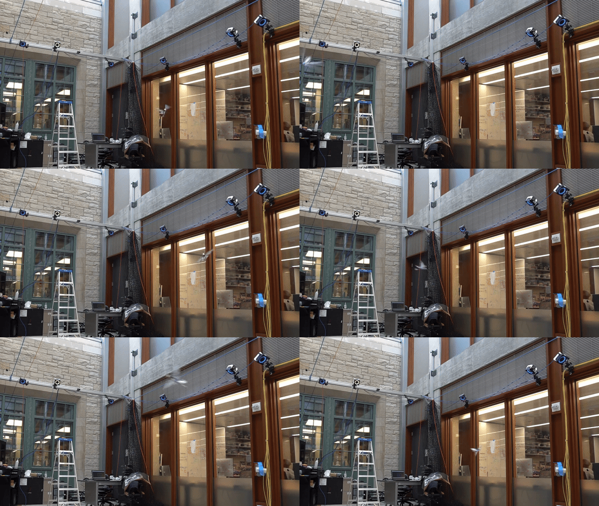
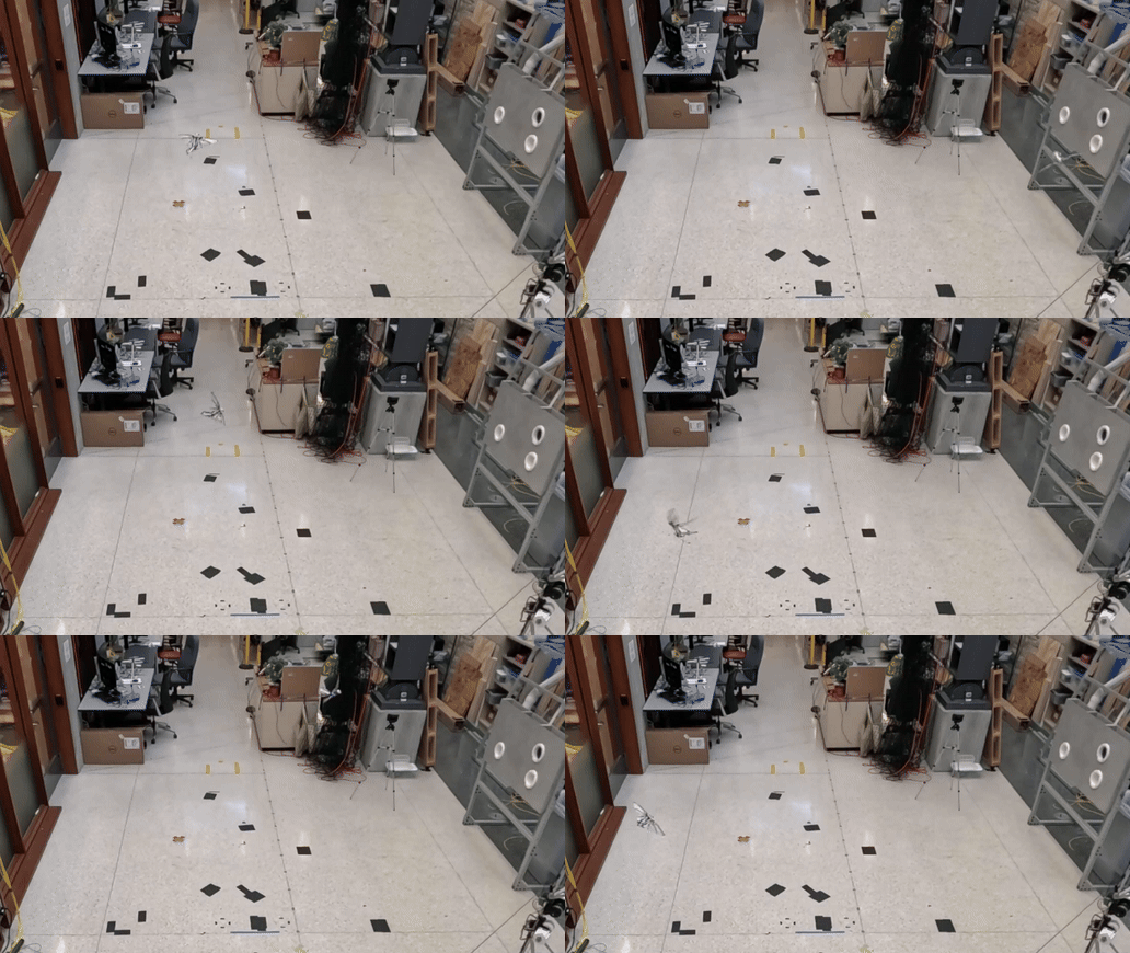
MetaFly by Bionic Bird
The MetaFly is a very cool biomimetic aerial platform sold by the company Bionic Bird. The thrust and lift vectors of this are coupled (somewhat like a fixed wing airplane) which means that it’s practically impossible for it to hover in place. The RF transmitter can send it speed and steering commands. The speed command indicates an increase/decrease in the flapping speed which makes the bird travel faster and higher, or slower and lower. The steering command works by a) moving the tail which creates a yawing drag moment, and b) by warping the wings in an asymmetrical manner which creates a difference in lift creating a rolling thrust moment… or at least I think it does.
MetaFly product video.
How hard is it to fly this thing?
While it flies really well in outdoor open spaces, it’s really hard to fly it outside when there is any wind (which is pretty much always in Chicago), and next to impossible to fly it for any duration longer than 10 seconds in an indoor environment. Here’s a snippet from my YouTube video of my friends trying to fly this device in an indoor space.
Control Architecture
The control architecture was developed after several hours of experimentation, involving tradeoffs between efficacy and complexity. In a nutshell, after carefully observing the bird in all of these trials, the following empirical rules guided my design of the controller:
- The bird takes speed and steering commands at every instant, and the wings flap fast enough for their actual position to not be significant.
- The bird follows a screw-like trajectory, and its direction of motion is within some cone of the direction it’s facing. The characteristics of this trajectory are not only a function of the commands sent to the bird, but also the bird’s current state, and external factors like wind.
- At large steering commands, the bird cannot generate enough lift and starts to descend.
- At smaller steering commands, the bird can be treated as two parallel Single Input Single Output (SISO) systems, as opposed to a general Multi Input Multi Output (MIMO) system. Here, the speed dictates the vertical velocity, and the roll dictates the radius of turning, with very little variance.
The motivation behind these rules is discussed in greater detail in the the Data Collection section.
At the heart of the control architecture is an altitude (\(z\)) controller that commands speed (\(\sigma\)), and a roll (\(\alpha\)) controller that outputs steering (\(\phi\)). The controller is exactly described by:
\[\begin{equation} \sigma = \sigma_{d}~+~K_{p_z}(z_t - z), \end{equation}\] \[\begin{equation} \phi = K_{p_{\alpha}}(\alpha_t - \alpha)~+~K_{d_{\alpha}}(\dot{\alpha}_t - \dot{\alpha}), \end{equation}\]where \(\sigma_d\) is the feedforward speed command required to maintain altitude. Here, the desired roll (\(\alpha_t\)) is either:
\[\begin{equation} \alpha_t = \alpha_d + K_{p_{R}}(R_t - R), \end{equation}\]or
\[\begin{equation} \alpha_t = \alpha_d + K_{p_{\gamma}}(\gamma_t - \gamma), \end{equation}\]decided by the motion planner, which also calculates the desired yaw (\(\gamma_t\)) and the desired radius (\(R_t\)). More on this in the Motion Planner section. The radius and yaw errors are multiplied by negative terms because an increase in roll implies a decrease in radius, or a decrease in yaw. The tunable parameters of this architecture are: \(\{K_{p_z}, K_{p_\alpha}, K_{p_R}, K_{p_\gamma}, K_{d_\alpha}, \sigma_{d}, \alpha_d\}\), which are distributed across controllers making them relatively easy to tune. There are more tunable parameters in the motion planner.

Motion Planner
The goal of the motion planner is to counteract the overall drift in the system that accumulates over time, to prevent the bird from violating the constraints of the room. It basically emulates a throw back towards the center, if the bird strays too far from the center / too close to the walls. It works by switching the behaviour over long time horizons, since experiments with reactive approaches did not acheive good results. This also relies on a special elliptical manifold which functions as a mixture of the target circle and cuboidal constraints of the drone cage. This aproach does not have a strong theoretical motivation, although an objective-based blending controller that mimics the functionality of this motion planner might be a less contrived and a more general approach. The tunable parameters for this are:
- The center and dimensions of the ellipse
- The center and radius of the target circle
- The range about the tangent for the heading vector
The pseudocode for the motion planner is:
1
2
3
4
5
6
7
8
9
10
11
12
13
14
15
START

ENABLE a height controller for speed command

IF the bird is inside the ellipse:
  ENABLE a radius controller for steering command, to track the target circle's radius

OTHERWISE:
  IF the tangent vector from the bird to the target circle is within a certain range of the bird's heading vector:
    ENABLE a yaw controller to make the bird travel along the tangent

  OTHERWISE:
    ENABLE a radius controller to make a sharp turn, so that it doesn't stray too far from the ellipse

GO TO START
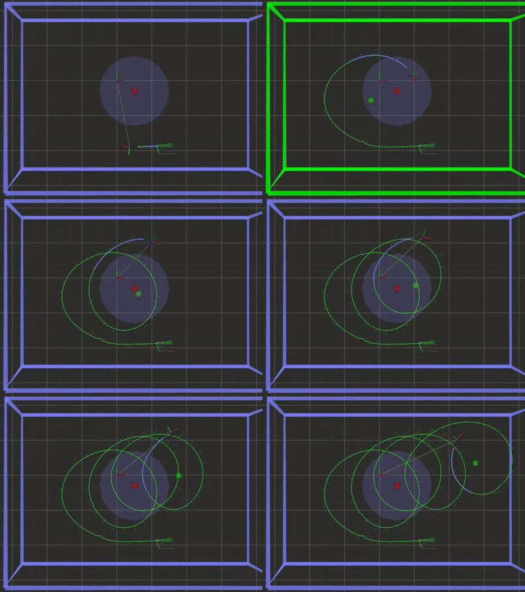
Here’s a video of the motion planner in action.
The motion planner in action, viewed through RViz. The bounding box is green when the bird is inside the ellipse, and mauve when the bird is outside it.
System Design
The system comprises: ROS 2 Network on a Linux Device, transmitter module for MetaFly, Windows machine with the OptiTrack, and the MetaFly itself, which form a closed loop together:

Transmitter - Feedforward
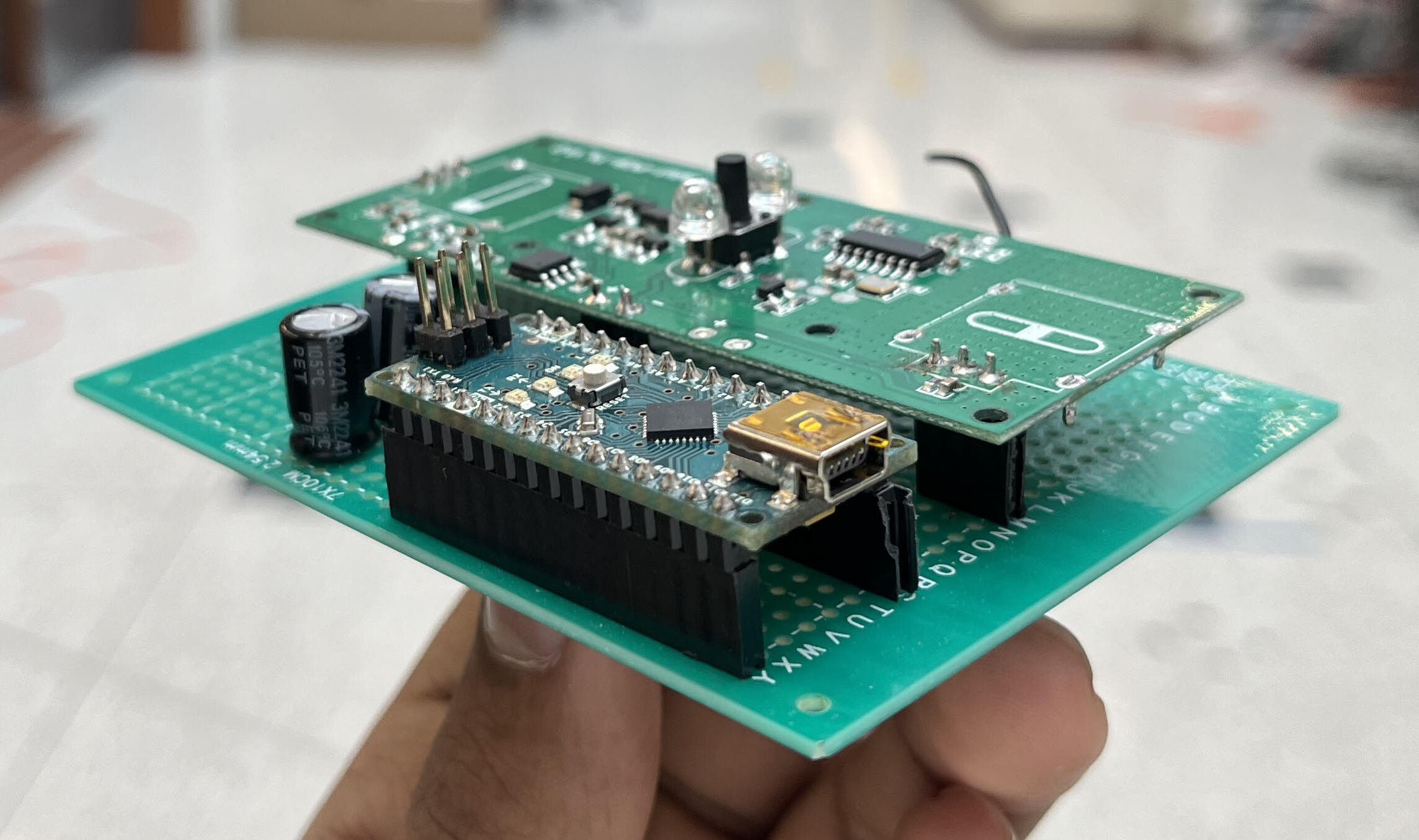
The transmitter module consists of an Arduino Nano, the MetaFly remote controller’s PCB with its potentiometers removed, and a small circuit which fits everything together as interchangeable shields. Its job is to take speed and steering commands through serial communication and transmit them to the bird. The Arduino’s analog outputs are used in parallel with large capacitors to emulate a potentiometer’s signal. I picked a Nano over a Teensy or something else of higher quality because it’s cheap and easy to replace.

Motion Capture - Feedback
The OptiTrack system is incredibly useful for aerial vehicles with a small payloads, but because the MetaFly weighs ~10g and has barely any payload, I had to create my own retroreflective markers using styrofoam balls and retroreflective tape.
These weighed 1/5th of similar-sized standard motion capture markers (~0.2g vs ~1g in my case).
I have not rigorously analyzed the payload capacity of the MetaFly.
After attaching these to the bird in whatever manner you want, you can register your bird as a rigid body by placing it at the origin of the motion capture system with the bird aligned with the X-axis.
You can fix its orientation by putting it in the charging position on the remote.
If you require, the ROS 2 listener node can also add a fixed transform offset to the bird’s pose using the pose_offsets.yaml file.
I also built a drone cage around the OptiTrack system using ropes and baseball nets.
A broadcaster script (credited to Drew Curtis) on the windows machine sends UDP pose messages over an ethernet connection to the ROS 2 listener node. This connection is what causes the largest delay in the system and a wireless connection in its place would perform even poorer, therefore an ethernet connection is required for real time control.
Follow these steps to use the metafly_listener package for publishing pose messages from the OptiTrack system to your ROS 2 network:
- Open Motive on Windows and only select your rigid body in the “Assets” tab.
- Make sure streaming is on, and that the “local interface” is set to “loopback”. Alternatively, you can simply import this motive profile.
- Connect your Linux Device via ethernet to the Windows device, and run this command on the Linux device:
1
  sudo ifconfig eno0 192.168.1.2 netmask 255.255.255.0 up
- Run the broadcaster script on you windows machine. It should keep spitting out info.
- Launch the
listener.launch.pyfile from themetafly_listenerpackage. You should see real time pose info on the/metafly_posetopic.
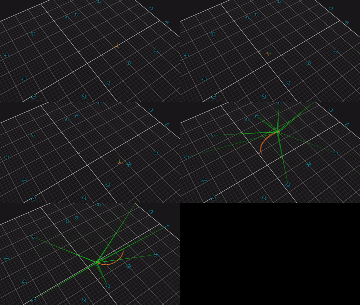
The initial motion capture setup used 10 cameras and did not cover enough of the drone cage. I attached and refocused 6 more cameras to get more complete coverage. This is what the observable workspace looked like after this:
Fig. 4. The portion of the drone cage that is observable using the OptiTrack system.
Experiments
The process of developing the final control architecture involved a lot of trial and error. Here are some of the main ideas/perspectives I discovered that were the most crucial in guiding me towards the final architecture.
Screw Trajectory
The lowest rung in the ladder for sustained flight in a closed space is flying in a circle. Given that the steering of the bird involves warping of the wings which affects the lift it can generate, the bird ends up ascending and descending along a screw trajectory. Assuming that this screw’s axis is aligned with the Z-axis, the radius, pitch and center of this screw trajectory can be measured by fitting a circle over the X and Y coordinates of a fixed horizon of trajectory points.
Screw-like trajectory of the robot. The green dot represents the instantaneous center on the x-y plane.
Data Collection
The controls domain comprises integer values for speed (\(0~\mbox{-}~127\)) and steering (\(-127~\mbox{-}~127\)). Using the perspective of all trajectories being screw trajectories, I tried to characterize them across the steering domain at a constant speed input.
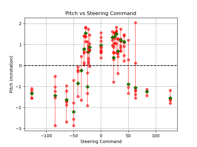
First, I found out that a higher steering angle generally translates to a negative pitch, and a lower steering angle translates to a positive pitch. This validated the physical viability of our goals by confirming the possibility of a closed trajectory with no net decrease in altitude.
Second, I observed that the turning radius is closely and predictably associated with the roll of the bird, and that positive steering always translates to positive roll i.e. banking left always makes it turn left, and vice versa. This indicated that the bird’s roll might be a promising parameter to control.
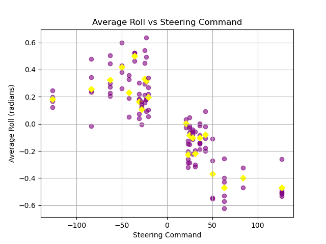
Since we don’t want the bird to decrease in height too much, we prefer to operate in a lower steering command range (\(\phi \approx -70~\mbox{-}~70\)).
Future Work
UPDATE: Check out the capabilities of the latest MetaFly here!
There are many possible offshoots that this work can be a foundational block in. Some that come to mind are:
1. Reactive Drift Control
If the bird is facing a direction that it isn’t moving in, there is an external factor like wind causing drift. This can be (naively) calculated using a velocity triangle:
\(V_{drift} = V_{actual} - V_{thrust}\).
I use the word naive because the direction and magnitude of \(V_{thrust}\) is not known (to me), and there might be second order dynamical relationships that can’t be ignored.
The real advantage is that this would allow the bird to track any arbitrary closed trajectory. I tried various reactive approaches but was not able to find one that made a noticeable improvement.
2. Imitation Learning through Data Collection
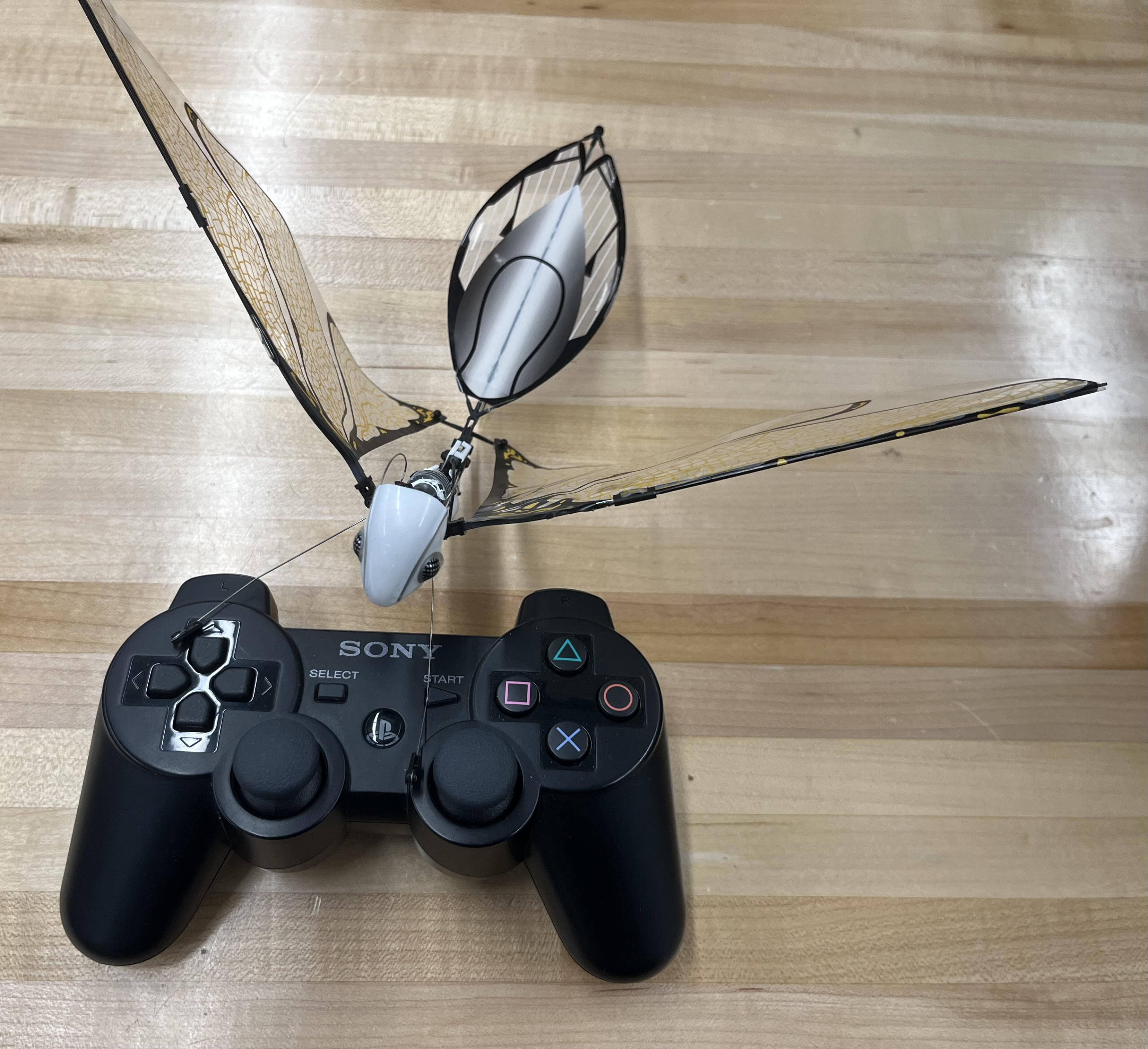
Since, the bird can now be controlled through a PS3 controller whose inputs can be recorded, it might lend itself well to some sort of imitation learning. While this was difficult to justify for a direct flight approach since humans are really bad at flying this thing, it might actually be highly relevant for tuning a motion planner that builds off of this. Eg. If the user observes the bird drifting to one side over time, they could push a joystick to move the ellipse in the opposite direction. Given the right context, this could train a model to “learn the wind”.
3. Tuning gains “on the fly”
In a similar sense, this could be used as a platform for testing/benchmarking learning methods that specialize in limited data to learn the tuning parameters while it is flying. This idea also stems from the concept behind birds learning how to fly, where they literally have to learn it in the first shot.
4. Transitioning from one set of constraints to another
The current system is reminiscent of a fly buzzing around a certain point of interest. It would be fun if someone could figure out how to make it transition from one point of interest and set of constraints, to another.
5. Minimal radius control
The smaller the circle, the less likely it is to crash into a wall. Currently when the bird is in the ellipse, it just targets a fixed radius, instead of the tightest possible radius while still maintaining level. This might be straightforward next step on my approach so far.
6. Hovering
It would be insanely cool to watch this thing hover! Maybe not instantaneously… but at least over a large horizon.
7. Not relying on the OptiTrack
If you can figure out a way to add some sort of onboard sensing unit, that would at the very least sense its orientation, this thing could be taken outdoors. This can also be used a platform for collecting data for training a model that improves the capability of a subpar sensor towards sensing pose / nearby obstacles. If flies can do this, then why can’t we?
🫵 Hey MSR students, I’m looking at you guys to get these done! 🫵
Acknowledgements

Thanks Jake, for mentoring me throughout this project, and for being so nice. You’re someone I can really talk to :)
Thanks Davin, for helping me build a totally epic DRONE CAGE!!

Thanks Drew, for helping me set up and debug the OptiTrack system.